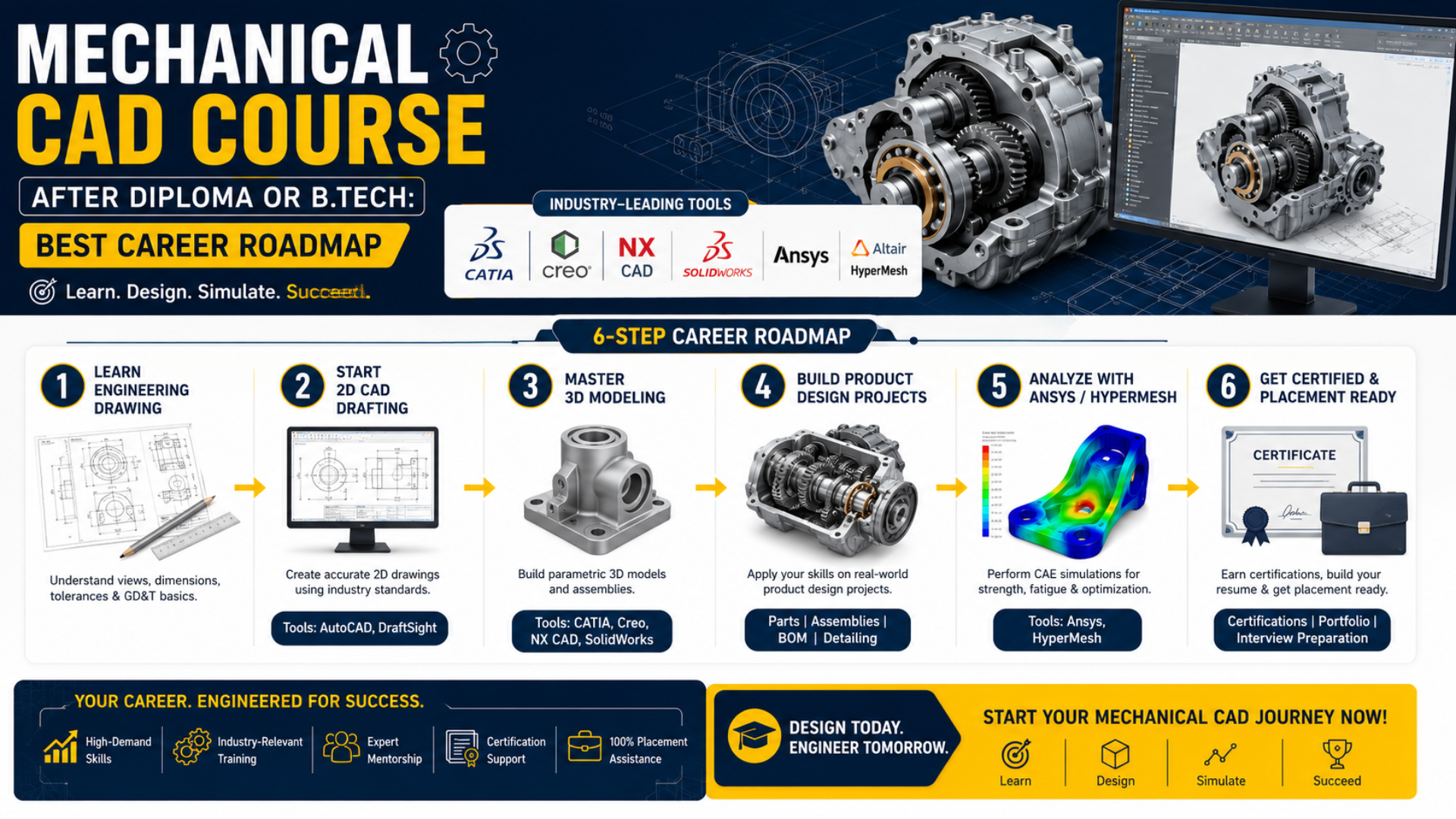
A Mechanical CAD course after a diploma or B. Tech is one of the most practical learning paths for students who want to build a career in mechanical design, product development, manufacturing, or engineering analysis. The best roadmap is to begin with engineering drawings and 2D drafting, learn one major 3D mechanical design software, practice assemblies and manufacturing drawings, complete product design projects and then add analysis tools such as Ansys or HyperMesh based on your career goal. Students do not need to learn every mechanical CAD software at the beginning. They should select the right combination of tools based on whether they want to work in product design, automotive design, manufacturing, tool design, or computer-aided engineering. Caddesk Hyderabad’s Mechanical CAD category includes AutoCAD Mechanical, CATIA, Creo, NX CAD, SolidWorks, Ansys, and HyperMesh, along with related mechanical and building-services courses.
Is Mechanical CAD a Good Career Choice After a Diploma or B.Tech?
Yes. Mechanical CAD is useful for both diploma and B.Tech graduates because it converts the engineering concepts learned in college into practical design skills.
During an engineering course, students learn subjects such as:
Engineering drawing
Machine design
Manufacturing technology
Strength of materials
Theory of machines
Thermodynamics
Material science
Production engineering
A mechanical design course helps students apply these concepts as they create components, assemblies, production drawings, and digital product models.
For example, instead of only studying a gear, bracket, flange, or shaft theoretically, students learn how to:
Prepare the engineering drawing.
Create an accurate 3D model.
Assign dimensions and tolerances.
Assemble it with other components.
Check whether the parts fit correctly.
Prepare drawings for manufacturing.
Analyze its behavior under loads.
This practical application is especially valuable for fresh graduates who have academic knowledge but limited experience with industry design workflows.
What Is Mechanical CAD Course ?
Mechanical CAD means using computer-aided design software to create, modify, analyze, and document mechanical components and products.
It can be used for:
2D mechanical drafting
3D part modeling
Assembly modelling
Sheet-metal design
Surface modelling
Product visualisation
Manufacturing drawings
Bill of Materials preparation
Design validation
Finite element analysis
Meshing and simulation preparation
Mechanical CAD is not limited to drawing. Modern design workflows can cover multiple stages, from the initial product concept to detailed modeling, simulation, and manufacturing documentation.
Who Can Learn a Mechanical CAD Course?
A Mechanical CAD course is suitable for:
Diploma mechanical engineering students
B.Tech or B.E. mechanical engineering students
Production engineering students
Automobile engineering students
Aeronautical engineering students
Mechatronics students
Tool and die-making students
Manufacturing professionals
Quality engineers
CNC and production professionals
Mechanical engineers planning to change careers.
Graduates preparing for design-related jobs
Diploma students can focus on drafting, modeling, and manufacturing drawings, as well as entry-level design roles. B.Tech students can follow a broader roadmap that includes product design, advanced assemblies, simulation, design calculations, and engineering analysis.
Mechanical CAD Course Roadmap After Diploma or B.Tech
The following step-by-step roadmap can help students learn mechanical CAD in the correct order.
Before learning advanced software, students should understand the fundamentals of engineering drawings.
Important topics include:
Types of lines
Drawing scales
Orthographic projections
Isometric views
Sectional views
Auxiliary views
Dimensioning methods
Limits, fits, and tolerances.
Surface-finish symbols
Welding symbols
Geometric Dimensioning and Tolerancing
Assembly drawings
Manufacturing drawings
Software commands become easier to understand when students know why a particular view, tolerance, symbol, or section is required.
GD&T is particularly important because manufacturing teams need more than a component’s basic size. They also need information about allowable variation, orientation, position, form, and relationships between features.
Step 2: Learn AutoCAD Mechanical for 2D Drafting
The next stage is learning AutoCAD Mechanical or an equivalent 2D drafting application.
Students should practice:
Drawing mechanical components
Creating multiple views
Preparing sectional drawings
Applying dimensions
Using mechanical symbols
Adding tolerances
Creating layers and templates
Preparing title blocks
Creating assembly drawings
Generating a Bill of Materials
Preparing print-ready drawings
AutoCAD Mechanical is useful for building accuracy and understanding how drawings communicate design requirements to production and manufacturing teams.
The Caddesk Mechanical CAD course page highlights machine parts, assemblies, detailed engineering drawings, dimensioning, tolerances, mechanical symbols, and Bill of Materials as part of the practical AutoCAD Mechanical learning process.
Step 3: Choose One Core 3D Mechanical Design Software
After learning 2D drafting, students should choose one main 3D CAD platform.
The right choice depends on the target industry and job role.
SolidWorks
Part modelling, assemblies, drawings, sheet metal and product documentation
Product design, machinery, equipment and manufacturing
CATIA
Complex parts, assemblies, surfaces and product development
Automotive, aerospace and advanced product design
Creo
Parametric modelling, assemblies and engineering design
Manufacturing, industrial products and machine design
NX CAD
Advanced modelling, assemblies and integrated design workflows
Automotive, aerospace, product engineering and manufacturing
Ansys
Structural, thermal and other engineering simulations
CAE, simulation and design validation
HyperMesh
Geometry preparation, meshing and finite-element model building
CAE pre-processing and simulation support
SolidWorks
SolidWorks is a suitable starting point for students who want to learn 3D product modeling through an accessible interface.
Students can learn:
Sketch creation
Parametric modelling
Part design
Assembly creation
Exploded views
Sheet-metal components
Weldments
Production drawings
Design documentation
SolidWorks officially describes its 3D CAD capabilities as covering detailed parts and assemblies, as well as production-ready documentation throughout the product development process.
CATIA
CATIA is commonly selected by students interested in advanced mechanical product design, complex assemblies, and surface modeling.
The learning path can include:
Sketch-based modelling
Part design
Assembly design
Drafting
Wireframe modelling
Surface design
Product structure
Mechanism concepts
Complex product development
CATIA supports product design and engineering processes ranging from product creation to simulation, while its engineering environment supports the creation of complex 3D assemblies.
Creo
Creo is useful for students who want to build strong parametric product-design skills.
Important learning areas include:
Parametric sketches
Feature-based modelling
Part design
Assembly constraints
Family tables
Sheet-metal design
Surface modelling
Drawing generation
Design modifications
PTC describes Creo as a family of 3D CAD applications for addressing product-design challenges and generating 3D geometry and engineering drawings.
NX CAD
NX CAD is suitable for students interested in advanced product engineering and integrated design and manufacturing workflows.
Students may learn:
Parametric part modeling
Direct modelling
Assembly design
Surface modelling
Sheet-metal design
Drafting
Product documentation
Design changes
Manufacturing-oriented workflows
Siemens describes NX as an integrated CAD and CAM solution that helps designers and manufacturers develop products using connected digital workflows.
Step 4: Learn Part Modeling Properly
Learning software commands alone is not sufficient. Students should understand the logic behind creating stable and editable models.
Part-modeling practice should cover:
Design intent
Fully defined sketches
Parent-child relationships
Reference planes
Extrude and revolve features.
Holes and patterns
Fillets and chamfers
Shell and rib features
Sweeps and lofts
Feature order
Model modification
Design configurations
A good model should not fail whenever a dimension is changed. Students must learn how to create models that can be modified without rebuilding the entire component.
Step 5: Learn Assembly Modeling
A mechanical product usually contains multiple parts. Assembly modeling helps students understand how those components are positioned and connected.
Students should learn:
Bottom-up assemblies
Top-down design basics
Assembly constraints
Degrees of freedom
Subassemblies
Component relationships
Interference detection
Clearance checking
Exploded views
Assembly drawings
Bill of Materials generation
Possible assembly projects include:
Bench vice
Universal coupling
Gearbox
Piston and connecting-rod assembly
Flange coupling
Screw jack
Mechanical clamp
Conveyor mechanism
Robotic gripper
Machine-tool fixture
Assembly projects are important because they show that a student can understand an entire product rather than only model individual components.
Step 6: Learn Manufacturing Drawings and Documentation
A 3D model becomes more valuable when it is supported by accurate production documentation.
Students should practice creating:
Part drawings
Assembly drawings
Sectional views
Detail views
Auxiliary views
Center marks and centrelines
Dimensions
Fits and tolerances
GD&T symbols
Surface-finish requirements
Welding information
Material specifications
Notes and revision tables
Bill of Materials
Balloon annotations
This stage connects CAD modeling with real manufacturing requirements.
Step 7: Understand Manufacturing Processes
Mechanical designers should have basic knowledge of how their components will be manufactured.
Important processes include:
Turning
Milling
Drilling
Grinding
Casting
Forging
Welding
Sheet-metal fabrication
Injection moulding
CNC machining
Additive manufacturing
Heat treatment
Surface finishing
Knowledge of manufacturing helps students avoid impractical designs.
For example, a model may look correct on a computer but still be difficult or expensive to manufacture. Designers should consider tool access, standard material sizes, wall thickness, draft angles, bend allowance, machining tolerances, and assembly sequence.
Step 8: Learn Ansys for Engineering Analysis
Students interested in simulation, product testing, or CAE can add Ansys after building a solid foundation in CAD and engineering mechanics.
The Ansys learning roadmap can cover:
Geometry import
Material assignment
Meshing
Boundary conditions
Loads and supports
Static structural analysis
Thermal analysis
Modal analysis
Result interpretation
Stress and deformation evaluation
Factor-of-safety concepts
Ansys defines finite element analysis as a method of predicting how an object behaves using calculations based on the finite element method. Ansys Mechanical provides capabilities for structural, thermal, transient, nonlinear, and other analyses.
Students should not simply run a simulation and accept the coloured result. They must understand whether the loads, supports, material properties, mesh, and assumptions are correct.
Step 9: Add HyperMesh for a CAE Career
HyperMesh is useful for students who want to move towards CAE pre-processing, meshing, or simulation-model preparation.
Students can learn:
Importing CAD geometry
Geometry cleanup
Defeaturing
Midsurface extraction
One-dimensional meshing
Two-dimensional meshing
Three-dimensional meshing
Shell meshing
Solid meshing
Mesh-quality parameters
Connectors
Model organisation
Solver-deck preparation
Model validation
Altair’s official learning documentation covers CAD preparation, geometry cleanup, midsurfacing, model building, and multiple meshing workflows in HyperMesh.
HyperMesh should normally be learned after students understand basic CAD geometry, engineering mechanics, and finite element analysis concepts.
Step 10: Complete Product Design Projects
Projects are one of the most important parts of a Mechanical CAD course after a diploma or B.Tech.
A strong project should demonstrate:
Understanding of the design requirement
Creation of individual parts
Proper assembly
Manufacturing feasibility
Drawing preparation
Material selection
Design calculations
Design modifications
Simulation or validation where required
Final presentation
Beginner Project Ideas
Flange coupling
Bearing block
Mechanical bracket
Pulley
Shaft
Knuckle joint
Cotter joint
Bench vice
Intermediate Project Ideas
Screw jack
Gearbox assembly
Machine vice
Mechanical press
Conveyor assembly
Fixture design
Robotic gripper
Sheet-metal enclosure
Advanced Project Ideas
Automotive suspension component
Steering mechanism
Industrial gearbox
Injection-molded product
Special-purpose machine concept
Product redesign for weight reduction
Structural analysis of a mechanical component
Design and simulation of a lifting mechanism
Students should document the entire process, not just final screenshots.
How to Create a Mechanical CAD Portfolio
A portfolio helps employers understand what the student can do practically.
Each portfolio project should contain:
Project title
Design problem or objective
Initial sketch or reference
Software used
Part models
Assembly model
Exploded view
Manufacturing drawings
Bill of Materials
Design calculations
Simulation results, where applicable
Final observations
Students should include approximately three to five well-developed projects rather than filling their portfolio with dozens of basic practice models.
The portfolio can be presented as a PDF, printed booklet, or structured digital folder.
Certification and Placement Preparation
Course certification can confirm that a student has completed structured training, but certification alone does not guarantee a job.
Employers are also likely to evaluate:
Software knowledge
Engineering drawing skills
Modelling speed
Accuracy
Understanding of manufacturing
Ability to explain projects
Problem-solving skills
Portfolio quality
Communication skills
Students should prepare for practical tests involving:
Creating a model from a drawing
Generating a drawing from a model
Assembling multiple components
Identifying modeling errors
Applying tolerances
Explaining design intent
Reading an engineering drawing
Answering manufacturing questions
At Caddesk Hyderabad, students can explore the Mechanical CAD course category, practical software training, product design learning paths, certification, and available placement support options. The Mechanical CAD page specifically lists certification and placement support for relevant course offerings.
Career Options After a Mechanical CAD Course
Depending on the selected software, projects, and engineering background, students can prepare for roles such as:
Mechanical CAD Designer
Mechanical Draughtsman
Junior Design Engineer
Product Design Engineer
CAD Engineer
Assembly Design Engineer
Sheet-Metal Designer
Tool Design Engineer
Fixture Design Engineer
Automotive Design Trainee
CAD Modeller
CAE Engineer
FEA Analyst
Meshing Engineer
Design Documentation Engineer
Manufacturing Design Engineer
Freshers may begin in junior or trainee roles and progress by developing stronger product knowledge, software expertise, and project experience.
Which Mechanical CAD Software Should You Learn?
The choice should be based on the target role.
For 2D Mechanical Drafting
Start with:
AutoCAD Mechanical
Engineering drawing
GD&T
Manufacturing drawings
For General Product Design
Choose:
SolidWorks or Creo
Assembly design
Sheet metal
Production drawings
Product-design projects
For Automotive or Aerospace Design
Consider:
CATIA or NX CAD
Advanced assemblies
Surface modelling
Product structure
Manufacturing documentation
For CAE and Simulation
Follow this sequence:
One CAD tool
Strength of materials
FEA fundamentals
Ansys
HyperMesh
For Manufacturing-Oriented Roles
Focus on:
AutoCAD Mechanical
Creo, SolidWorks or NX
GD&T
Machining knowledge
CNC fundamentals
Design for manufacturing
Why Choose Mechanical CAD Training in Hyderabad?
Hyderabad has students and working professionals from mechanical, production, automobile, aerospace, and manufacturing backgrounds.
Joining structured mechanical CAD training in Hyderabad can provide access to:
Instructor-guided learning
Practical laboratory sessions
Multiple mechanical software options
Doubt clarification
Product-design projects
Portfolio guidance
Certification
Interview preparation
Placement assistance
Classroom learning with other engineering students
Caddesk Hyderabad offers Mechanical CAD training in Ameerpet, and lists separate learning options for AutoCAD Mechanical, CATIA, Creo, NX CAD, SolidWorks, Ansys, and HyperMesh.
Recommended Mechanical CAD Learning Combinations
Roadmap for Diploma Students
Engineering drawing
AutoCAD Mechanical
GD&T
SolidWorks or Creo
Part and assembly projects
Manufacturing drawings
Certification and interview preparation
Roadmap for B.Tech Students
Engineering drawing revision
AutoCAD Mechanical
GD&T
CATIA, Creo, NX or SolidWorks
Advanced assemblies
Product-design project
Ansys fundamentals
Portfolio preparation
Certification and placement preparation
Roadmap for CAE Aspirants
Engineering mechanics
Strength of materials
One 3D CAD software
FEA fundamentals
Ansys
HyperMesh
Structural-analysis projects
CAE portfolio and interview preparation
Frequently Asked Questions
Is a Mechanical CAD course useful after a diploma?
Yes. A Mechanical CAD course after a diploma helps students develop practical drafting, modeling, assembly, and manufacturing-drawing skills. It can support preparation for roles such as mechanical drafter, junior CAD designer, and design trainee.
Is Mechanical CAD useful after B.Tech Mechanical Engineering?
Yes. B. Tech graduates can use CAD training to convert academic engineering knowledge into practical product-design, manufacturing, and analysis skills.
Which software should a mechanical fresher learn first?
A fresher can begin with AutoCAD Mechanical and engineering drawing. The next step is to choose one of the 3D software packages, such as SolidWorks, Creo, CATIA, or NX, based on the target industry.
Should I learn CATIA, Creo, NX, and SolidWorks together?
It is not necessary to learn all four at the beginning. Select one core 3D tool, become confident in part modeling, assemblies, and drawings, and complete practical projects. Additional software can be learned later when required by a job role.
Which is better: CATIA or SolidWorks?
Neither software is universally better. SolidWorks can be suitable for general product design, machinery, and manufacturing applications. CATIA is well-suited for complex product structures, advanced assemblies, and surface design workflows. The right choice depends on the intended career.
Do I need AutoCAD before learning CATIA or Creo?
AutoCAD is not technically mandatory, but learning 2D drafting and engineering drawing first can make it easier to understand dimensions, sections, views, and production documentation.
Is Ansys part of Mechanical CAD?
Ansys primarily belongs to the field of computer-aided engineering and simulation. It complements CAD by helping engineers analyze how a component may behave under structural, thermal, or other operating conditions.
What is the role of HyperMesh?
HyperMesh is used for preparing finite-element models. It supports geometry cleanup, midsurface creation, meshing, model organization, and preparation for engineering solvers.
Can Mechanical CAD students get jobs without experience?
Freshers can apply for trainee and junior positions, but they should demonstrate practical ability through projects, drawings, and a structured portfolio.
Is a certificate enough to get a Mechanical CAD job?
No. A certificate can strengthen the resume, but students must also demonstrate software knowledge, engineering understanding, project experience, and the ability to complete a practical design test.
What projects should I include in my portfolio?
Include projects that demonstrate part modeling, assembly creation, manufacturing drawings, and problem-solving. A gearbox, mechanical fixture, screw jack, sheet-metal enclosure, or product redesign can be more valuable than a collection of unrelated basic models.
Final Mechanical CAD Career Roadmap
A successful Mechanical CAD career should be built step by step:
The objective should not be to collect software certificates. It should be to understand how a mechanical product is designed, documented, manufactured, and validated. Students who combine software skills with engineering fundamentals, manufacturing knowledge, and practical projects can build a stronger profile for mechanical design, product development, and CAE opportunities.
Start Your Mechanical CAD Learning Journey at Caddesk Hyderabad
Caddesk Hyderabad offers Mechanical CAD learning options for diploma students, B.Tech graduates, freshers, and working professionals.
Students can explore training in:
AutoCAD Mechanical
GD&T
CATIA
Creo
NX CAD
SolidWorks
Ansys
HyperMesh
Product design
Mechanical engineering projects
The training path can be selected based on the student’s educational background, existing skills, and career objectives. Visit the Caddesk Hyderabad Mechanical CAD course page to explore course options, practical training, certification, project guidance, and placement-support information.
CADDESK HYDERABAD
Caddesk Hyderabad
Caddesk Hyderabad Is the Best AutoCAD Training Institute in Hyderabad